Metal–organic frameworks, constructed by inorganic nodes (metal ions or clusters) with organic linkers, have attracted great attention over the past two decades as a promising class of porous solid materials1,2). MOFs have several unique properties, such as high surface area, tunable composition, and versatile functionality, which have provided them with high potential in a variety of fields3–9), especially in catalysis10,11).
The inorganic nodes of MOFs can behave as transition metal catalysts. The inorganic units are well isolated and homogeneously distributed throughout the framework. The porous structure of MOFs allows the free diffusion of substrates to access the active sites. Moreover, the solid MOFs can be well recyclable after catalytic runs. Therefore, MOFs combine the advantages of homogeneous catalyst with full usage of active sites and high reactivity and heterogeneous catalysts with good recyclability.
The pore surface of MOFs can be rational functionalized through direct or post modification12). The inorganic nodes can immobilize active species (e.g., inorganic acidic groups, organic molecules, and metal complexes) and be exchanged with other catalytically active metal nodes13,14). The organic linkers can be functionalized with catalytically active organic groups, which can further immobilize metal complexes for catalysis. The well-developed methodologies for the functionalization of MOF pore surface have greatly enhance the catalytic performance of MOFs.
The pore structure of MOFs provides a great opportunity to immobilize a variety of guest species15–17), such as metal nanoparticles (NPs)18,19). The control of the size, location, composition, and shape of metal NPs within MOFs can greatly improve the properties of the metal NP@MOF composites20). Furthermore, the tuning of the interactions between metal NPs and MOFs is important to activity and stability improvement.
Moreover, MOFs can act as outstanding precursors/templates for the synthesis of nanostructures by high-temperature pyrolysis21–23). Since our report on the use of MOFs as precursors/templates for synthesis of porous carbons in 200824), a variety of nanomaterials have been synthesized from MOFs, including carbon, metal oxides, metal/metal chalcogenides/metal phosphides on carbon, and metal on metal oxides. MOF-derived nanostructures have shown high chemical and mechanical stabilities, large specific surface areas, tunable pore structures and various functionalities, which have greatly extended the catalytic applications of MOFs, especially in electrocatalysis25–27).
The present article summarizes the research progress of our group on the developments of pristine MOFs, metal NP@MOF composites and MOF derivatives for catalytic applications. We have comprehensively discussed the design, synthesis, structure, and catalytic performance of the MOF-based materials, aiming to establish the structure–performance relationship. Finally, we present an outlook and prospective for future works with MOF-based materials for catalytic applications.
2. Pristine MOFs for Catalysis
Pristine MOFs can be used directly as catalysts28). The inorganic nodes of MOFs can act as metal catalyst and the organic linkers containing free functional groups can act as organocatalysts29–31). Typically, when using the inorganic nodes of MOFs as metal catalyst, the inorganic nodes of MOFs should have coordination positions available for the binding and activation of substrates. Only a few of as-synthesized MOFs can be directly used as catalysts, allowing the exposure of the metal ions to substrates by an expansion of their coordination sphere or a reversible displacement of the organic linkers32). Usually, further treatment is required to expose the inorganic nodes through removal of labile ligand (e.g., solvent molecules and modulators) to fabricate coordinatively unsaturated sites (CUSs) as Lewis acid catalysts. Relevant examples of this type of MOFs, such as HKUST-1(Cu3(btc)2(H2O)3, H3btc=1,3,5-benzenetricarboxylic acid)33), MIL-101(Cr3F(H2O)2O[(O2C)-C6H4-(CO2)]3)34), UiO-66(Zr)35), can generate Lewis acid sites after the removal of labile ligands, which have been successfully applied in a variety of chemical transformations, including liquid-phase29,36) and gas-phase reactions37,38).
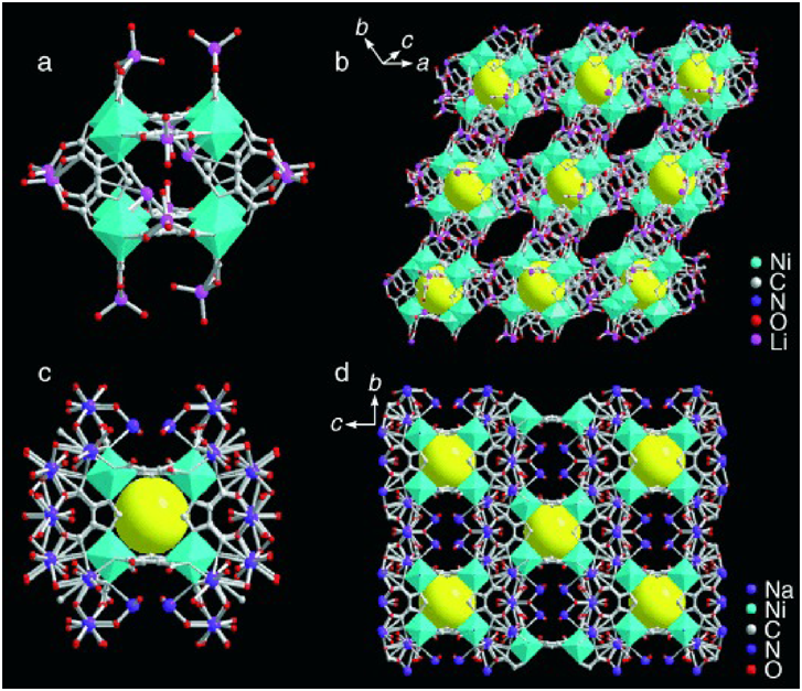
In 2006, we reported the first example of porous MOFs as catalysts for the gas-phase transformation37). We constructed the functional MOFs by using the discrete metal–organic cubic building block [Ni8L12]20−(H3L=4,5-imidazoledicarboxylic acid), bridged by alkali-metal ions (Li+ and Na+)(Fig. 1). The obtained MOF bridged by NaI ions exhibited high and stable catalytic activity in the CO oxidation to CO2. The reaction rate and the activation energy over the MOF catalyst were between those of NiO and Ni-Y zeolite. In addition, the MOF catalyst showed stable activity for the initial 20 minutes, while the activity of Ni-Y zeolite and NiO decreased rapidly and took more than 50 minutes to reach steady state.
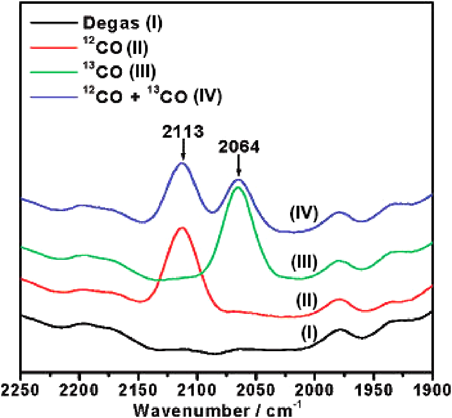
In the subsequent study, we constructed a new MOF, Cu (mipt)(mipt=5-methylisophthalate), possessing coordinated-unsaturated Lewis acid sites on the interior of channel walls, which exhibited highly active and stable catalytic performance in the oxidization of CO to CO238). After activation at 250°C in air for 3 h, the as-synthesized MOF catalyst showed 100% CO conversion at 200°C. The activity of the MOF catalyst was similar or higher than those of CuO and CuO/Al2O3. The acidity of the MOF catalyst was examined by 12CO and 13CO isotopic probe molecules (Fig. 2). IR spectra showed the formation of mono-CO species on the Cu center in the dehydrated MOF, while the signal was not observed in the nonhydrated MOF.
3. MOF Composites for Catalysis
The porous structure of MOFs enables MOFs to immobilize a variety of catalytically active guest species in the pores, which can greatly enhance their catalytic activity15–17). Metal NPs with high chemical activity and specificity have attracted great attention to be immobilized in/on MOFs for the synthesis of MOF–metal NP composites18,39). It has been demonstrated that the size, location, composition, and shape of metal NPs in MOFs can greatly determine the performance of the MOF–metal NP composites40–43). Therefore, it is of great importance to control the nucleation and growth processes of metal NPs in MOFs. In this regard, our group have developed a variety of effective strategies to immobilize mono- and bimetallic NPs in MOFs, which have shown high catalytic activity, selectivity and stability in many catalytic transformations, including oxidation of CO, hydrogenation, dehydrogenation of chemical hydrogen storage materials.
3.1 MOFs immobilized monometallic NPs
In 2009, we reported the deposition of Au NPs on ZIF-8(Zn(MeIM)2, MeIM=2-methylimidazole) with a simple solid grinding method44). ZIF-8 and volatile organogold complex (CH3)2Au(acac), acac=acetylacetonate) was first ground uniformly in air, followed by treatment in a stream of 10 vol% H2 in He at 230°C for 2.5 h to yield Au@ZIF-8. The obtained Au@ZIF-8 composites were catalytically active in CO oxidation (Fig. 3). With the increase of Au loadings, the activity of the Au@ZIF-8 composites improved, as demonstrated by the decrease of the temperatures for 50% conversion (225, 200, 185, and 170°C, for 0.5, 1.0, 2.0, and 5.0 wt% Au@ZIF-8 composites, respectively). This work represents the first example of a porous MOF immobilized noble metal NPs for gas phase catalysis. In order to prepare low cost and efficient catalysts, we further synthesized and investigated the catalytic performance of MOFs immobilized non-noble metal NPs. In 2012, we reported the immobilization of highly dispersed Ni NPs on ZIF-8 via a sequential deposition–reduction method45). The obtained Ni/ZIF-8 composites showed high catalytic activity and durability in the hydrolysis of aqueous ammonia borane (NH3BH3, AB) for hydrogen generation. At room temperature, 19.0 wt% Ni/ZIF-8 could completely transform AB to H2 in 13 min, giving a turnover frequency (TOF) value of ~14.2 molH2 molNi−1 min−1. Moreover, no significant decrease in catalytic activity could be observed even after 5 runs. This work presents the first successful example of MOF-supported metal catalysts for the dehydrogenation of AB.
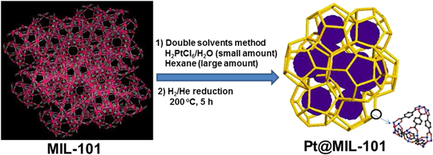
Traditional methods for the synthesis of metal NPs in MOFs would inevitably afford metal NPs deposited on the external surface of MOFs, which would easily aggregate during the reaction condition, resulting in catalyst deactivation. To address this challenge, we have developed a “double solvents” method to immobilize ultrafine Pt NPs inside the pores of MIL-101 without aggregation of Pt NPs on the external surface of framework46). This method is based on the dissolution of metal precursors (H2PtCl6) in a hydrophilic solvent (water) with a volume set equal to or less than the pore volume of the adsorbent (MIL-101) and a hydrophobic solvent (hexane) in a large amount to suspend the adsorbent and facilitate the impregnation process (Fig. 4). Further treatment in a stream of H2/He (50 mL min−1/50 mL min−1) at 200°C for 5 h yielded Pt@MIL-101. Electron tomographic reconstruction showed that Pt NPs with an average size of 1.8±0.2 nm were uniformly distributed in MIL-101 framework. The as-synthesized Pt@MIL-101 exhibited excellent catalytic activities for reactions in all three phases (i.e., liquid-phase AB hydrolysis, solid-phase AB pyrolysis, and gas-phase CO oxidation). In the hydrolysis of AB, 2 wt% Pt@MIL-101 completely converted AB to H2 within 2.5 min, with a TOF value of 1.0×10⁴ LH2 molPt−1 min−1. In the pyrolysis of AB, AB dehydrogenation in the pores of Pt@MIL-101 showed lower dehydrogenation temperature and higher H2 selectivity compared with pure AB and pristine MIL-101. In CO oxidation, Pt@MIL-101 also showed high activity, achieving complete conversion of CO at 150°C. This work represents the first example of highly active MOF-immobilized metal nanocatalysts for catalytic reactions in all three phases. The “double solvents” method has been successfully extended to the synthesis of Pd NPs within MOFs. The obtained Pd@MOF composites showed high activity and stability in reduction of 4-nitrophenol (4-NPh) by sodium borohydride (NaBH4)47), hydrodeoxygenation of vanillin48), reduction of Cr (VI) using formic acid49).
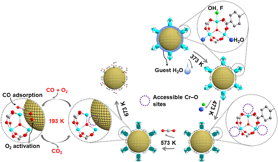
The interactions between metal NPs and MOFs play an important role in determining the reactivity of metal NP@MOF composites. However, in the pores of MOFs, the presence of organic linkers separates the inorganic nodes from the guest metal NPs, resulting in weak interactions between MOFs and the immobilized metal NPs. Very recently, we demonstrated a new concept of “quasi-MOFs” fabricated through a controlled deligandation process, which could realize both a porous structure and a strong interaction between the inorganic nodes and the guest metal NPs50). As a proof of concept, we calcined Au/MIL-101 at different temperatures (i.e., 373, 473, 573, 673, and 1073 K) under an inert atmosphere to tune the interface between Au NPs and inorganic Cr–O nodes (Fig. 5). Characterizations demonstrated that MIL-101 underwent release of guest H2O at 373 K, followed by removal of coordinated H2O and OH/F groups on the Cr–O nodes at 473 K, consequent release of CO2 from the terephthalate ligand to form quasi-MIL-101 at 573 K, and finally collapse of the framework along with carbon formation above 673 K. In the CO oxidation, the calcined Au/MIL-101 samples showed enhanced activity compared with the non-calcined Au/MIL-101. With the increase of calcination temperatures from 373 to 573 K, the catalytic activity increased. Further increasing the calcination temperature above 673 K resulted in a remarkable decrease in activity. Au/MIL-101(573) exhibited the highest activity, maintaining 100% CO conversion up to 1700 min. The exhibited superior catalytic performance of Au/MIL-101(573) is due to the enhanced metal–support interaction to show synergistic effect between the accessible Cr–O sites and Au NPs to cooperatively activate O2 and CO molecules to form CO2. This controlled deligandation-transformation strategy is a general method for the fabrication of quasi-MOFs, which can greatly improve the performance of existing MOFs.
3.2 MOF immobilized bimetallic NPs
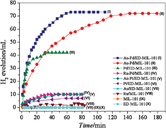
Upgrading the monometallic NPs to bimetallic NPs with controlled compositions can largely enhance the properties due to the bimetallic synergistic effects51,52). In 2011, we immobilized bimetallic Au–Pd NPs in MIL-101 and ethylenediamine (ED)-grafted MIL-101(ED-MIL-101) using a simple liquid impregnation method coupled with reduction under a H2/He stream53). In the hydrogen generation from formic acid, Au–Pd/MIL-101 could completely convert 140 mg of formic acid to H2 and CO2 in 145 min at 90°C(Fig. 6). Further grafting the electron-rich functional group ethylenediamine (ED) into MIL-101could improve the interactions between the metal NPs and the MIL-101 support, thus allowing Au–Pd/ED-MIL-101 to show superior catalytic activity (with complete conversion in 65 min). Under the similar reaction condition, Au/ED-MIL-101 had no catalytic activity and Pd/ED-MIL-101 released only 10% hydrogen due to catalyst poisoning by CO, implying the synergistic effect between Pd and Au. Moreover, Au–Pd/ED-MIL-101 showed high stability/durability, with the productivity of hydrogen remained almost unchanged after five runs. This work represents the first example of highly active MOF-immobilized metal catalysts for hydrogen generation from chemical hydrogen storage materials.
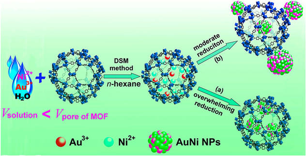
Considering that the cost of noble metals will restrict their practical applications, the introduction of a transition metal to afford bimetallic NPs can not only reduce the usage of noble metal, but also elicit unique properties. However, non-noble metal precursors have low reduction potentials thus require high reduction temperatures when using hydrogen reduction method, which is not suitable for MOFs with low thermal stabilities. In this regard, we have developed a liquid-phase concentration-controlled reduction (CCR) strategy coupled with the “double solvents” method to control the size and location of non-noble based metal NPs in the pores of MOFs (Fig. 7)54). Au3+ and Ni2+ precursors were first introduced into the pores of MIL-101 by the “double solvents” method. When a high concentration of reductant (NaBH4) solution was employed, ultrafine AuNi alloy NPs were successfully encapsulated into the MOF pores without aggregation on the external surface. In contrast, using a low concentration of NaBH4 solution resulted in serious agglomeration of AuNi alloy NPs on the external surface of MOFs. In the hydrolytic dehydrogenation of ammonia borane, AuNi@MIL-101 catalysts gave a TOF value of 66.2 molH2 molcat−1 min−1, which was higher than that of AuNi/MIL-101 with some AuNi NPs deposited on the external surface (35.3 molH2 molcat−1 min−1). AuNi@MIL-101 catalysts showed higher activity compared with the monometallic counterparts, attributing to a synergistic effect between Au and Ni. Moreover, AuNi@MIL-101 showed high durability, keeping the activity almost unchanged after five runs. This work opens new avenues for developing MOFs immobilized ultrafine metal NPs, especially non-noble metal-based NPs, for catalytic applications. Moreover, we further extended this method to the immobilization of other non-noble metal-based alloy NPs (e.g., AuCo55)and RuNi56))and non-noble bimetallic alloy NPs (e.g., CuCo57))in MIL-101, showing high catalytic activity and durability for hydrogen generation from dehydrogenation of AB.
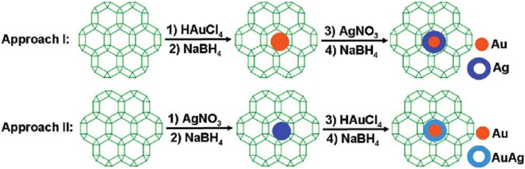
Bimetallic core–shell NPs have attracted a great attention due to their unique properties and specificities, which are different from their monometallic counterparts and alloy. However, it is more challenging to immobilize bimetallic core–shell NPs to MOFs. In 2011, we reported, for the first time, the immobilization of core–shell Au@Ag NPs on ZIF-8 by a sequential deposition–reduction method58). The synthesis of Au@Ag core–shell NPs on ZIF-8 was proceed via sequentially immersing ZIF-8 in aqueous solutions of Au and Ag precursors, with respective reduction and drying (Fig. 8). The reversed deposition sequence for Ag and Au yielded Au@AuAg NPs. In the reduction of 4-nitrophenol by NaBH4, monometallic Au/ZIF-8 showed no catalytic activity, and Ag/ZIF-8 proceeded slowly with “induction period”. The catalytic activity was significantly improved by using core–shell Au@Ag/ZIF-8 as catalysts. Further tuning the ratio of Au/Ag pointed to an optimized Au/Ag ratio of 2/2, showing the highest activity with a rate constant to be 4.97×10⁻³ s−1. This work opens a new avenue in the development of MOFs supported bimetallic core–shell NPs for catalytic applications.
3.3 MOF immobilized polyhedral metal nanocrystals
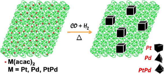
Metal nanocrystals with different facets can show extremely different chemistries. The immobilization of polyhedral metal nanocrystals on MOFs can greatly broaden the metal NP@MOF family to show promising properties for catalytic applications. In 2013, we reported for the first time the fabrication of polyhedral metal nanocrystals on MOFs by a CO-directed reduction strategy59). M(acac)2(M = Pt, Pd or Pt/Pd) was first impregnated into the preactivated MIL-101 by incipient wetness method, followed by treatment in a stream of CO/H2/He (40/10/50 mL min−1) at 200°C for 1 h to produce Pt/MIL-101, Pd/MIL-101, and PtPd/MIL-101(Fig. 9). Transmission electron microscopy (TEM) showed that most of the metal crystals in Pt/MIL-101, Pd/MIL-101 and PtPd/MIL-101 were cubic (88%), tetrahedral (80%), and octadedral (65%), respectively. During the reduction process, CO directed the growth of metal nanocrystals. Due to the stronger binding of CO molecules to Pt (100) and Pd (111) facets, the growth of Pt (100) and Pd (111) planes were inhibited, resulting in the formation of cubic Pt and tetrahedral Pd nanocrystals. In the CO oxidation reaction, all the MIL-101 supported metal nanocrystals were found to be highly active. Pt/MIL-101, Pd/MIL-101, PtPd/MIL-101, and Pt@Pd/MIL-101 achieved the complete conversion of CO at 175, 200, 175, and 200°C, respectively. This work opens a new avenue in the development of MOF immobilized metal nanocrystals with different shapes and compositions for heterogeneous catalysis.
4. MOF Derivatives for Catalysis
MOFs can be used as precursors/templates for the synthesis of nanostructured materials (such as porous carbons, metal oxides, metal/carbon, metal/metal oxide). Since our report in 200824), the thermal transformation strategy has enabled the synthesis of a variety of functional nanomaterials with good performance in many fields, especially in catalysis.
4.1 Porous carbon-based materials
In 2008, we demonstrated the synthesis of porous carbons using MOF-5 as a precursor/template and furfuryl alcohol (FA) as an additional carbon source24). Degassed MOF-5 was first heated at 150°C in FA vapor, allowing FA to be polymerized in the pores of MOF-5. The polymerized FA/MOF-5 composite was calcined at 1000°C for 8 h under an Ar flow. During the calcination process, Zn metal vaporized away, leaving carbon species alone. The obtained carbon material showed a large Brunauer–Emmett–Teller (BET) surface area (2872 m2 g−1) and a large pore volume (2.06 cm3 g−1). In the subsequent study, we detailed studied the influence of the carbonization temperature to specific surface area, pore size distribution, and electrical conductivity of the obtained carbon materials60). MOF-5 accommodated FA was carbonized at five different temperatures, e.g., 530, 650, 800, 900, 1000°C. With the increase of carbonization temperatures, the BET surface areas showed a “V” shape. In addition, among all the carbon materials, the carbon material obtained by carbonization at 530°C showed poor electrical conductivity due to the low carbonization temperature.
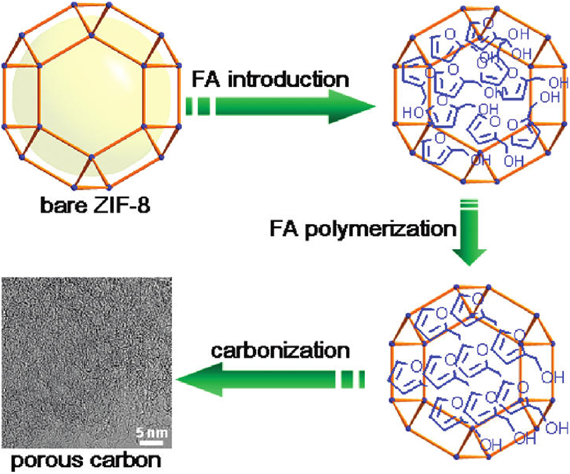
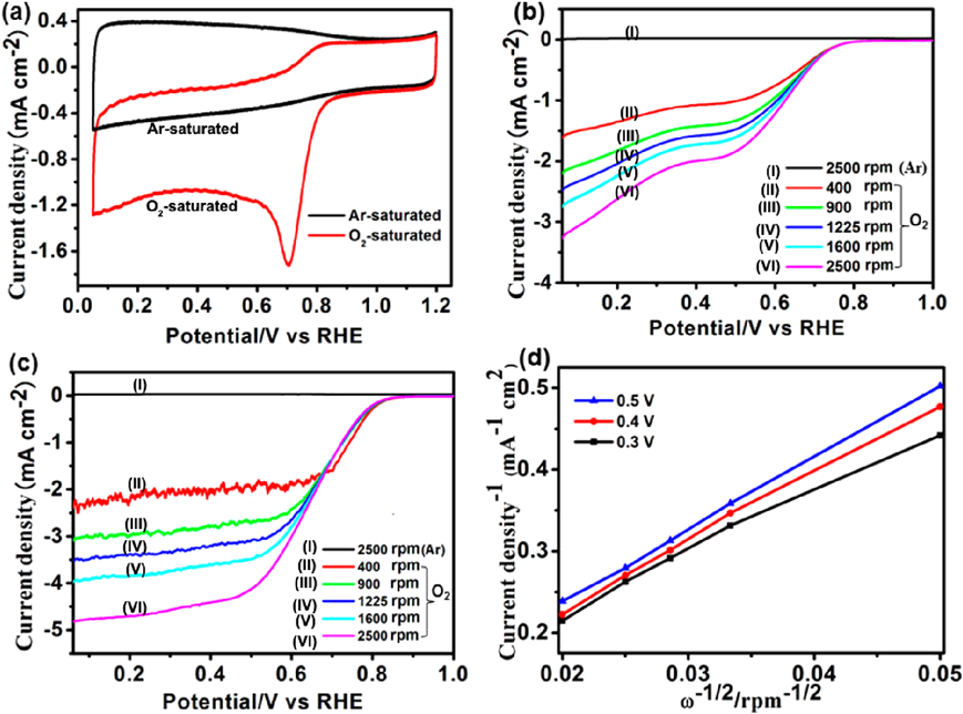
The doping of heteroatoms in carbon structures can enhance the properties of carbon materials. Heteroatom-containing MOFs (e.g., ZIFs) can be employed as precursors/templates to synthesis heteroatom-doped carbon materials in one step. In this regard, we used N-containing ZIF-8 as both a precursor and a template and FA as a second precursor to prepare N-doped porous carbon (Fig. 10)61). The carbon material obtained by carbonization at 1000°C possessed a large BET surface area of 3405 m2/g and a pore volume of 2.58 cm3/g. Another strategy to synthesize heteroatom-doped carbon is introducing heteroatom precursors (e.g., small organic molecules62)and ionic liquids63))into the pores of MOFs to act as heteroatom sources in the carbonization process. In 2014, we synthesized N-doped carbon materials using ZIF-8 as a template and precursor along with furfuryl alcohol and NH4OH as the secondary carbon and nitrogen sources, respectively62). FA and NH4OH were first introduced into the cavities of activated ZIF-8, followed by calcination at different temperatures (e.g., 600, 700, 800, 900, or 1000°C)with subsequent HF washing to N-decorated carbon materials (denoted as NCx, x represents the calcination temperature). NC900 and NC1000 had moderate N contents, high surface areas, and large numbers of mesopores, while NC800 had a high N content, a moderate surface area, and large numbers of micropores. In the oxygen reduction reaction (ORR), NC700, NC800, NC900, and NC1000 showed onset potentials at 0.71, 0.76, 0.83, and 0.82 V, respectively (Fig. 11). The Koutecky–Levich plots showed that N-rich NC800 favored the two-electron reduction process, while NC900 and NC1000 with moderate N favored the four-electron reduction pathway. This work shows the great potential of heteroatom-doped carbons derived from MOFs in electrocatalysis.
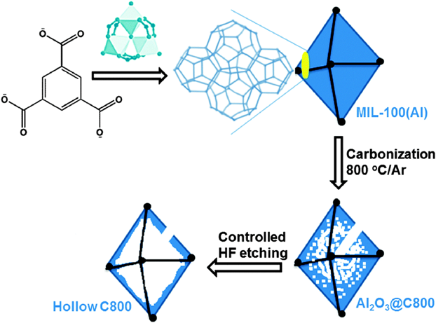
The control of pore structures of carbon materials is important for their on-demand applications. The carbon materials derived from MOFs contain mainly micropores, which are unfavorable for substrate diffusion in catalytic applications. We have developed several strategies to synthesize porous carbon materials with a hierarchical structure with micro- and mesopores derived from MOFs. In 2014, we developed a ultrasonication treatment strategy to assemble microporous ZIF-8 particles into hierarchically porous ZIF-8 frameworks, which could be transformed to 3-dimensional (3D) hierarchically porous carbon materials with micro-, meso- and macropores64). The large pores in the carbon materials were originated from the spaces between the assembled ZIF-8 particles. Alternatively, meso- and macropores can be fabricated through post acid etching treatment after carbonization of MOFs. We reported the synthesis of hollow polyhedral carbons by using a mesoporous MOF as a precursor/template followed by a controlled acid etching treatment65). As a proof of concept, MIL-100(Al), Al3O(OH)(H2O)2(btc)2, was calcined at 800°C, followed by hydrofluoric acid (HF) washing to give hollow carbons (Fig. 12). Pore size distribution showed that the pore sizes of the obtained carbon mainly centered at 1–3 nm, with a peak centered at ~33 nm, reflecting the hollow nature of carbon frameworks. Moreover, we recently demonstrated that the surface area and pore volume could be greatly enhanced through incorporation of pore-structure-directing agent, such as chitosan (CS)66). CS was incorporated into MOF-5 during the synthesis of MOF, followed by pyrolysis in an argon flow at 900°C and a subsequent acid treatment to remove the metal impurities to give hierarchically porous carbons (NPC). The obtained NPC showed a high surface area (2375 m2 g−1) a high total pore volume (2.49 cm3 g−1), and a high Vmeso-macro/Vmicro ratio (1.47). For compassion, direct pyrolysis of MOF-5 resulted in a lower surface area (1578 m2 g−1), a lower total pore volume (1.37 cm3 g−1), and a lower Vmeso-macro/Vmicro ratio (0.73). Very recently, we demonstrated that energetic MOFs (EMOFs) could act as precursors/templates for the synthesis of carbon networks with hierarchically porous structures induced by a large amount of gases generated during decomposition of the energetic ligands67). A triazole-based EMOF [Zn-(C2N3H2)2] was doped with transition metal (Co, Fe, or CoFe), which was further carbonized to give atomically dispersed metal sites decorated carbon networks (CoFe@C). In ORR, the obtained CoFe@C showed a more positive half-wave potential than that of commercial Pt/C in 0.1 M KOH electrolyte. Rotating ring disk electrode (RRDE) investigation showed that the electron transfer number was 3.9.
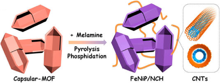
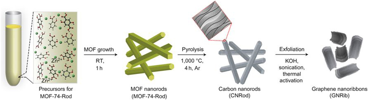
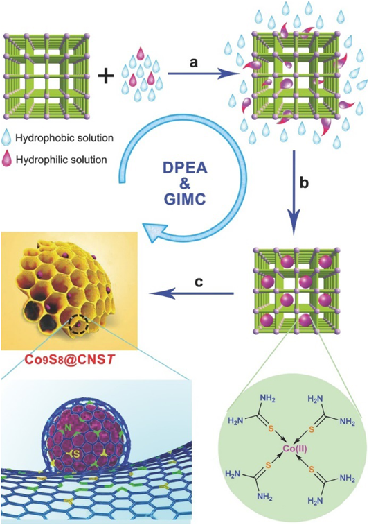
The morphology of carbon materials is a critical factor that determines their performance in catalytic applications. The morphology control of MOF-derived carbon materials is attractive, albeit challenging. In this regard, we have developed a variety of strategies to prepare MOF-derived carbon materials with diverse morphologies, including zero-dimensional (0D) polyhedral and capsular structures, 1D rods and hollow tubes, 2D sheets and ribbons; and 3D frameworks and honeycomb-like structures. For the synthesis of MOF-derived carbon composites with 0D capsular structures, we developed a self-templated strategy to successfully fabricate an Fe–Ni-based single-crystal open capsular-MOF, which could be transformed to FeNiP NPs embedded in open capsular carbons (FeNiP/NCH) through pyrolysis–phosphidation with melamine (Fig. 13)68). The as-synthesized FeNiP/NCH exhibited superior performance in oxygen evolution, hydrogen evolution, and oxygen reduction, and achieved well-qualified assemblies of an overall water splitting and a rechargeable Zn–air battery, outperforming FeNiP/NCS and FeNiP/C composites derived from solid MOF and FeNi-MIL-88B, respectively. In 2016, we fabricated 1D carbon nanorods by self-sacrificial and morphology-preserved thermal transformation of MOF-74 with rod-shaped morphology (Fig. 14)69). A subsequent sonochemical treatment followed by thermal activation of the carbon nanorods could yield 2D graphene nanoribbons with two- to six-layer thickness. Very recently, we fabricated single-crystal MOF nanotubes via an amorphous MOF-mediated recrystallization approach, which acted as templates/precursors along with dicyandiamide as a nitrogen and a secondary carbon source to give long carbon nanofibers wrapped by carbon nanotubes with Co NPs on the top70). The resulting composites exhibited excellent electrocatalytic activity for ORR, with a half-wave potential of 0.861 V vs RHE (RHE = reversible hydrogen electrode). From K–L plots, the electron transfer number was calculated to be 3.87–3.92 at potentials varying from 0.4 to 0.7 V. Furthermore, we fabricated a unique 3D honeycomb-like porous carbon nanostructure with immobilized Co9S8 NPs, using MOFs as templates/precursors and thiourea (TU) and CoCl2 as the secondary precursors (Fig. 15)71). TU and CoCl2 were introduced into the pores of MIL-101-NH2 via a double-phase encapsulation approach (DPEA), in which a hydrophilic solvent (methanol–water solution) dissolved TU and CoCl2 and hydrophobic solvent (n-hexane) facilitated the impregnation process. Co (II) TU@MIL-101-NH2 was carbonized at various temperatures under an Ar flow, followed by subsequent HF washing to give N and S dual-doped honeycomb-like porous carbons with immobilized Co9S8 NPs (denoted as Co9S8@CNST). Co9S8@CNS900 showed high electrocatalytic activities toward ORR, with a half-wave potential of −0.17 V, which was comparable to those of Pt/C(−0.15 V). From the K–L plots, the electron transfer number was calculated to be 3.94–3.99 at the potentials ranging from −0.40 to −0.60 V. We further extended the DPEA approach to the synthesis of atomically dispersed Fe/N-doped hierarchical carbon architecture72) and N and S co-doped hollow cellular carbon nanocapsules73) from MOF composites. Fe/N-doped hierarchical carbon exhibited high catalytic performance for oxygen reduction with a half-wave potential of −0.13 V, outperforming the benchmark Pt catalyst. K–L plots revealed an electron transfer number of ~4.0 at −0.4 to −0.6 V. Very recently, we fabricated a spherical superstructure of carbon nanorods (SS-CNR) derived from a spherical superstructure of MOF nanorods (SS-MOFNR)74). The obtained SS-CNR preserved the chestnut-shell-like superstructure originated from SS-MOFNR, with 1D porous carbon nanorods on the shell, which was used as a support for immobilizing ultrafine Pd NPs. In the dehydrogenation of FA, the as-synthesized Pd@SS-CNR showed an exceptionally high activity with a TOF of 7200 h−1 at 60°C, which was about 6.3 times to that of Pd@XC72. The exhibited superior performance of Pd@SS-CNR could be attributed to the unique features of hierarchical structure. The synthesis of carbon cages with an open-wall structure and good contact with each other is attractive. We constructed a hydrangea-like superstructure of open carbon cages through thermal transformation of metal ions doped core–shell MOFs75). Direct pyrolysis of core–shell Zn@Co-MOFs produced open-wall N-doped carbon cages. Further introducing guest Fe ions into the core–shell MOF precursor yielded open carbon cages assembled into a hydrangea-like 3D superstructure interconnected by carbon nanotubes. The as-synthesized composites exhibited superior electrocatalytic performances toward OER and ORR, outperforming the RuO2 and Pt catalysts, respectively.
4.2 Carbon immobilized noble metal NP composites
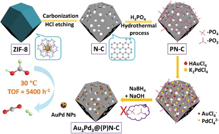
The carbon materials derived from MOFs can act as ideal supports to immobilize catalytically active metal NPs76–79). We immobilized Pd NPs on porous N-doped carbon obtained by direct carbonization of assembled ZIF-8 NPs at different temperatures, denoted as Pd/ZC-x (x=800, 900, 1000 and 1100°C)80). Pd NPs were uniformly distributed in ZC-1000 with an average size of 2.4 nm. For comparison, Pd NPs supported on commercial carbon black Vulcan XC-72R showed a larger size (3.0 nm). In the methanol electrooxidation reaction (MOR), the catalytic activity of Pd/ZC-1000(45.20 mA cm−2) was 5 times higher than that of Pd/XC-72R (9.20 mA cm−2). The superior activity of Pd/ZC-1000 could be attributed to the high surface area, good conductivity, nitrogen doping of the carbon support and ultrafine Pd NPs. Recently, we further demonstrated that an additional treatment with ultrasonication in aqueous potassium hydroxide (aq KOH) could yield a hierarchically porous carbon with micro- and mesopores to act as an excellent support for Pd NPs81). Al-MIL-101-NH2 was employed as a precursor to synthesize a N doped carbon composite at 900°C, followed by activation in aq KOH to remove Al2O3, which was employed as a support to immobilize Pd NPs (1.1±0.2 nm). Pd@CN900K showed high catalytic activity in the hydrogenation evolution from formic acid/sodium formate (FA/SF) solution, with a TOF value of 14400 h−1. Moreover, Pd@CN900K could retain its activity over 5 cycles. The heteroatoms in carbon structures play an important role in stabilizing the immobilized metal NPs. In previous studies, we demonstrated that N species on carbon supports could enhance the dispersibility of metal NPs (especially Pd NPs), while they are not sufficient for the dispersion of Au NPs. Very recently, we developed a phosphate-mediation approach to prepare highly active AuPd NPs on N-doped carbon materials (Fig. 16)82). ZIF-8 was carbonized at 1000°C under an Ar flow followed by a subsequent acid etching to afford a N-doped porous carbon. Then the N-doped carbon was treated with H3PO4 in H2O to give a phosphate-anchored carbon, which could anchor Au and Pd precursors strongly. The subsequent reduction of metal precursors in the alkaline solution removed the phosphate as well, affording highly dispersed AuPd NPs with a mean diameter of 1.5±0.4 nm on the carbon support (AuPd@(P) N-C). In the dehydrogenation of FA reaction, AuPd@(P) N-C displayed an excellent catalytic activity with a TOF value of 358.3 h−1 without the addition of SF at 30°C. Moreover, AuPd@(P) N-C showed high durability, with no loss of activity for ten cycles.
Metal NP@carbon composites can also be prepared through carbonization of metal NP@MOF composites. As a proof of concept, we synthesized Ru@HKUST-1 composites by one-pot solvothermal reaction of Cu and Ru precursors and H3BTC, followed by carbonization at 800°C to give Cu/Ru NPs (3–4 nm) embedded in carbon83). In the hydrolysis of AB, Cu/Ru@C showed high activity, giving a TOF value of 97 molH2 molcat−1 min−1 based on Ru. Moreover, Cu/Ru@C showed high stability and durability, with the productivity of H2 remained almost unchanged for five runs.
4.3 Metal oxide-based materials
In 2009, we demonstrated the first example of fabricating metal oxide NPs through a one-step pyrolysis of MOFs in air for the application as electrode materials for batteries84). A cobalt-based MOF, Co3(NDC)3(DMF)4(NDC=2,6-naphthalene- dicarboxylate; DMF=N,N’-dimethylformamide), was selected as a template to convert to cobalt oxide (Co3O4). The obtained agglomerated Co3O4 NPs showed an average diameter of 250 nm, which consisted of small NPs with a size of about 25 nm.
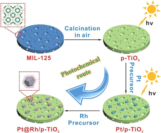
Metal NPs supported on metal oxides composites represent one major category of heterogeneous catalyst. Metal oxides derived from MOFs can be employed as excellent supports for immobilizing metal NPs. We employed porous TiO2 nanoplates derived from MIL-125 to immobilize core–shell Pt@Rh NPs via a two-step photochemical route (Fig. 17)85). The obtained Pt@Rh/p-TiO2 showed high catalytic activity in the hydrolytic dehydrogenation of AB, with a TOF value of 2441 molH2 molcat−1 min−1 at 30°C. We showed that metal/metal oxide composites could be synthesized through pyrolysis of metal impregnated MOFs86). Platinum salt was first introduced into the pores of MOF-5, followed by heating in air at 600°C to afford Pt/ZnO. The sizes of Pt NPs can be controlled by tuning the concentration of Pt precursors. When decreasing the concentration of Pt precursors from 0.1 to 0.025 to 0.005, the sizes of the obtained Pt NPs decreased from 10 to 5 to 2 nm, respectively, while the size of ZnO kept the same. In the CO oxidation, Pt/ZnO samples displayed high catalytic activity. Pt0.1/ZnO, Pt0.025/ZnO and Pt0.005/ZnO achieved complete CO conversions at 154, 160, and 140°C, respectively. The catalytic activity of Pt0.1/ZnO was twice as high as that of Pt/ZnO obtained by conventional methods. The superior activity of Pt/ZnO prepared by MOF route could be attributed to the stronger interaction between Pt and ZnO.
In this account, we have discussed recent advances with respect to pristine MOFs, metal NP@MOF composites, and MOF-derived nanomaterials for catalytic applications. Pristine MOFs with abundant coordinatively unsaturated metal sites can act as active Lewis acid catalysts in gas-phase transformation, such as CO oxidation. Porous MOFs can serve as excellent supports to immobilize catalytically active metal nanoparticles (NPs) to enhance the catalytic performance. We have developed several strategies, including “double-solvents” method, overwhelming reduction approach, and CO-direct reduction, to well control the sizes, locations, compositions, and shapes of metal NPs within MOFs. In this regard, monometallic NPs, bimetallic metal alloy NPs, bimetallic core–shell NPs, and polyhedral metal nanocrystals have been successfully immobilized in MOFs to significantly enhance the properties of metal NP@MOF composites. Furthermore, we have proposed a new concept of “quasi-MOFs” to greatly improve the interactions between guest metal NPs and inorganic nodes for enhanced catalytic performance. The metal NP@MOF composites have demonstrated to be excellent catalysts in many catalytic transformations, including oxidation of CO, hydrogenation, and dehydrogenation of chemical hydrogen storage materials. MOFs can be employed as precursors/templates for the synthesis of diverse nanomaterials, including carbon, metal/carbon, metal oxides, and metal/metal oxides. The control of the pore structure, morphology, and doping of the MOF-derived nanomaterials can regulate their electronic, physical and chemical properties and thus influence their catalytic performance.
Although tremendous efforts have been made and significant advances have been achieved regarding MOF-based materials for catalytic applications, there remain challenges in material synthesis and catalytic performance improvements to be addressed.
1) The stability issue of MOFs and MOF composites should be addressed. The mechanical and chemical stability is of vital importance for the shaping and reuse of catalyst in industrial applications. Strategies should be developed to enhance the stability of MOFs and MOF composites under the shaping and reaction condition.
2) The scalable and efficient methods for the synthesis of MOFs and MOF composites with high yield are required. A one-pot protocol is preferred, which can omit energy-consuming steps for the separation and purification of intermediates.
3) The improvement of the interactions between MOFs and guest active species is of vital importance for activity and stability enhancement. Quasi-MOFs with exposed inorganic nodes can offer stronger interactions with guest species than MOFs, which can open new avenues for the design of efficient catalysts.
4) The control of homogeneous doping and metal incorporation in the pyrolysis of MOFs and MOF composites is desired to achieve the highest efficiency and to understand the structure–performance relationship.
In the past decade, significant progresses have been made for the catalytic applications of functional MOFs, MOF composites and their derivatives. Continued research and development can be expected to enable the practical applications of MOF-based materials.
謝辞Acknowledgments
The authors thank the editor for the kind invitation. We would like to thank AIST for financial support.
Declaration of interests
The authors declare no competing interests.
引用文献References
1) S. Kitagawa, R. Kitaura, S.-i. Noro, Angew. Chem. Int. Ed., 43, 2334(2004).
2) H. Furukawa, K. E. Cordova, M. O'Keeffe, O. M. Yaghi, Science, 341, 974(2013).
3) H.-L. Jiang, Q. Xu, Chem. Commun., 47, 3351(2011).
4) S.-L. Li, Q. Xu, Energy Environ. Sci., 6, 1656(2013).
5) H. Wang, Q.-L. Zhu, R. Zou, Q. Xu, Chem, 2, 52(2017).
6) C.-C. Hou, Q. Xu, Adv. Energy Mater., 9, 1801307(2019).
7) X. Li, S. Zheng, L. Jin, Y. Li, P. Geng, H. Xue, H. Pang, Q. Xu, Adv. Energy Mater., 8, 1800716(2018).
8) R. Zhao, Z. Liang, R. Zou, Q. Xu, Joule, 2, 2235(2018).
9) H. Li, L. Li, R.-B. Lin, W. Zhou, Z. Zhang, S. Xiang, B. Chen, EnergyChem, 1, 100006(2019).
10) L. Jiao, Y. Wang, H.-L. Jiang, Q. Xu, Adv. Mater., 30, 1703663(2018).
11) D. Li, H.-Q. Xu, L. Jiao, H.-L. Jiang, EnergyChem, 1, 100005(2019).
12) C. Xu, R. Fang, R. Luque, L. Chen, Y. Li, Coord. Chem. Rev., 388, 268(2019).
13) X. Yang, Q. Xu, Cryst. Growth Des., 17, 1450(2017).
14) Y. Wen, J. Zhang, Q. Xu, X.-T. Wu, Q.-L. Zhu, Coord. Chem. Rev., 376, 248(2018).
15) Q.-L. Zhu, Q. Xu, Chem. Soc. Rev., 43, 5468(2014).
16) L. Chen, Q. Xu, Matter, 1, 57(2019).
17) L. Chen, R. Luque, Y. Li, Chem. Soc. Rev., 46, 4614(2017).
18) A. Aijaz, Q. Xu, J. Phys. Chem. Lett., 5, 1400(2014).
19) Q. Yang, Q. Xu, H.-L. Jiang, Chem. Soc. Rev., 46, 4774(2017).
20) L. Chen, R. Luque, Y. Li, Dalton Trans., 47, 3663(2018).
21) S. Dang, Q.-L. Zhu, Q. Xu, Nat. Rev. Mater., 3, 17075(2017).
22) J.-K. Sun, Q. Xu, Energy Environ. Sci., 7, 2071(2014).
23) L.-F. Chen, Q. Xu, Science, 358, 304(2017).
24) B. Liu, H. Shioyama, T. Akita, Q. Xu, J. Am. Chem. Soc., 130, 5390(2008).
25) W. Xia, A. Mahmood, R. Zou, Q. Xu, Energy Environ. Sci., 8, 1837(2015).
26) F.-Y. Yi, R. Zhang, H. Wang, L.-F. Chen, L. Han, H.-L. Jiang, Q. Xu, Small Methods, 1, 1700187(2017).
27) Z. Liang, R. Zhao, T. Qiu, R. Zou, Q. Xu, EnergyChem, 1, 100001(2019).
28) M. Fujita, Y. J. Kwon, S. Washizu, K. Ogura, J. Am. Chem. Soc., 116, 1151(1994).
29) K. Schlichte, T. Kratzke, S. Kaskel, Micropor. Mesop. Mater., 73, 81(2004).
30) J. S. Seo, D. Whang, H. Lee, S. I. Jun, J. Oh, Y. J. Jeon, K. Kim, Nature, 404, 982(2000).
31) C.-D. Wu, A. Hu, L. Zhang, W. Lin, J. Am. Chem. Soc., 127, 8940(2005).
32) I. Luz, A. León, M. Boronat, F. X. Llabrés i Xamena, A. Corma, Catal. Sci. Technol., 3, 371(2013).
33) S. S. Chui, S. M. Lo, J. P. Charmant, A. G. Orpen, I. D. Williams, Science, 283, 1148(1999).
34) G. Ferey, C. Mellot-Draznieks, C. Serre, F. Millange, J. Dutour, S. Surble, I. Margiolaki, Science, 309, 2040(2005).
35) F. Vermoortele, B. Bueken, G. Le Bars, B. Van de Voorde, M. Vandichel, K. Houthoofd, A. Vimont, M. Daturi, M. Waroquier, V. Van Speybroeck, C. Kirschhock, D. E. De Vos, J. Am. Chem. Soc., 135, 11465(2013).
36) L. Alaerts, E. Séguin, H. Poelman, F. Thibault-Starzyk, P. A. Jacobs, D. E. De Vos, Chem. Eur. J., 12, 7353(2006).
37) R.-Q. Zou, H. Sakurai, Q. Xu, Angew. Chem. Int. Ed., 45, 8086(2006).
38) R.-Q. Zou, H. Sakurai, S. Han, R.-Q. Zhong, Q. Xu, J. Am. Chem. Soc., 129, 8402(2007).
39) Q.-L. Zhu, Q. Xu, Chem, 1, 220(2016).
40) L. Chen, H. Chen, R. Luque, Y. Li, Chem. Sci., 5, 3708(2014).
41) L. Chen, X. Chen, H. Liu, Y. Li, Small, 11, 2642(2015).
42) L. Chen, B. Huang, X. Qiu, X. Wang, R. Luque, Y. Li, Chem. Sci., 7, 228(2016).
43) L. Chen, W. Huang, X. Wang, Z. Chen, X. Yang, R. Luque, Y. Li, Chem. Commun., 53, 1184(2017).
44) H.-L. Jiang, B. Liu, T. Akita, M. Haruta, H. Sakurai, Q. Xu, J. Am. Chem. Soc., 131, 11302(2009). Q1
45) P.-Z. Li, K. Aranishi, Q. Xu, Chem. Commun., 48, 3173(2012). Q2
46) A. Aijaz, A. Karkamkar, Y. J. Choi, N. Tsumori, E. Rönnebro, T. Autrey, H. Shioyama, Q. Xu, J. Am. Chem. Soc., 134, 13926(2012).
47) M. Yadav, A. Aijaz, Q. Xu, Funct. Mater. Lett., 05, 1250039(2012).
48) A. Aijaz, Q.-L. Zhu, N. Tsumori, T. Akita, Q. Xu, Chem. Commun., 51, 2577(2015).
49) M. Yadav, Q. Xu, Chem. Commun., 49, 3327(2013).
50) N. Tsumori, L. Chen, Q. Wang, Q.-L. Zhu, M. Kitta, Q. Xu, Chem, 4, 845(2018).
51) H.-L. Jiang, Q. Xu, J. Mater. Chem., 21, 13705(2011).
52) A. K. Singh, Q. Xu, ChemCatChem, 5, 652(2013).
53) X. Gu, Z.-H. Lu, H.-L. Jiang, T. Akita, Q. Xu, J. Am. Chem. Soc., 133, 11822(2011).
54) Q.-L. Zhu, J. Li, Q. Xu, J. Am. Chem. Soc., 135, 10210(2013).
55) J. Li, Q.-L. Zhu, Q. Xu, Chem. Commun., 50, 5899(2014).
56) S. Roy, P. Pachfule, Q. Xu, Eur. J. Inorg. Chem., 2016, 4353(2016).
57) J. Li, Q.-L. Zhu, Q. Xu, Catal. Sci. Technol., 5, 525(2015).
58) H.-L. Jiang, T. Akita, T. Ishida, M. Haruta, Q. Xu, J. Am. Chem. Soc., 133, 1304(2011).
59) A. Aijaz, T. Akita, N. Tsumori, Q. Xu, J. Am. Chem. Soc., 135, 16356(2013).
60) B. Liu, H. Shioyama, H. Jiang, X. Zhang, Q. Xu, Carbon, 48, 456(2010).
61) H.-L. Jiang, B. Liu, Y.-Q. Lan, K. Kuratani, T. Akita, H. Shioyama, F. Zong, Q. Xu, J. Am. Chem. Soc., 133, 11854(2011).
62) A. Aijaz, N. Fujiwara, Q. Xu, J. Am. Chem. Soc., 136, 6790(2014).
63) A. Aijaz, T. Akita, H. Yang, Q. Xu, Chem. Commun., 50, 6498(2014).
64) A. J. Amali, J.-K. Sun, Q. Xu, Chem. Commun., 50, 1519(2014).
65) A. Aijaz, J.-K. Sun, P. Pachfule, T. Uchida, Q. Xu, Chem. Commun., 51, 13945(2015).
66) S. Zhong, M. Kitta, Q. Xu, Chem. Asian J., DOI: 10.1002/asia.201900318(2019).
67) R. Zhao, Z. Liang, S. Gao, C. Yang, B. Zhu, J. Zhao, C. Qu, R. Zou, Q. Xu, Angew. Chem. Int. Ed., 58, 1975(2019).
68) Y.-S. Wei, M. Zhang, M. Kitta, Z. Liu, S. Horike, Q. Xu, J. Am. Chem. Soc., 141, 7906(2019).
69) P. Pachfule, D. Shinde, M. Majumder, Q. Xu, Nat. Chem., 8, 718(2016).
70) L. Zou, C.-C. Hou, Z. Liu, H. Pang, Q. Xu, J. Am. Chem. Soc., 140, 15393(2018).
71) Q.-L. Zhu, W. Xia, T. Akita, R. Zou, Q. Xu, Adv. Mater., 28, 6391(2016).
72) Q.-L. Zhu, W. Xia, L.-R. Zheng, R. Zou, Z. Liu, Q. Xu, ACS Energy Lett., 2, 504(2017).
73) Q.-L. Zhu, P. Pachfule, P. Strubel, Z. Li, R. Zou, Z. Liu, S. Kaskel, Q. Xu, Energy Storage Mater., 13, 72(2018).
74) L. Zou, M. Kitta, J. Hong, K. Suenaga, N. Tsumori, Z. Liu, Q. Xu, Adv. Mater., 31, 1900440(2019).
75) C.-C. Hou, L. Zou, Q. Xu, Adv. Mater., DOI: 10.1002/adma.201904689(2019).
76) J.-K. Sun, Q. Xu, ChemCatchem, 7, 526(2015).
77) W.-W. Zhan, Q.-L. Zhu, Q. Xu, ACS Catal., 6, 6892(2016).
78) Z. Li, Q. Xu, Acc. Chem. Res., 50, 1449(2017).
79) S. Zhong, Q. Xu, Bull. Chem. Soc. Jpn., 91, 1606(2018).
80) J. Li, Q.-L. Zhu, Q. Xu, Chem. Commun., 51, 10827(2015).
81) Q. Wang, N. Tsumori, M. Kitta, Q. Xu, ACS Catal., 8, 12041(2018).
82) Q. Wang, L. Chen, Z. Liu, N. Tsumori, M. Kitta, Q. Xu, Adv. Funct. Mater., 29, 1903341(2019).
83) P. Pachfule, X. Yang, Q.-L. Zhu, N. Tsumori, T. Uchida, Q. Xu, J. Mater. Chem. A, 5, 4835(2017).
84) B. Liu, X. Zhang, H. Shioyama, T. Mukai, T. Sakai, Q. Xu, J. Power Sources, 195, 857(2010).
85) W.-W. Zhan, Q.-L. Zhu, S. Dang, Z. Liu, M. Kitta, K. Suenaga, L.-S. Zheng, Q. Xu, Small, 13, 1603879(2017).
86) L. Bo, H. Song, T. Koji, S. Hiroshi, X. Qiang, Bull. Chem. Soc. Jpn., 82, 1052(2009).